Home
Sponsored Research
Current Expeditions
Past Expeditions
Publication Downloads
Become a Sponsor
Promotional Items
About USDCT
Contact

2024 Sistema Cheve
2023 Sistema Cheve
2022 Sistema Cheve
2021 Sistema Cheve
2019 Sistema Cheve
2018 Sistema Cheve
2018 Huautla PESH
2018 Peña Colorada
2017 Sistema Cheve
2013 J2
2010 J2
2009 J2
1998 Wakulla 2
About
Personnel and Sponsors
Technology
Digital Wall Mapper
Scooters
Rebreathers
Computer Graphics
Radio Location
Dive Lights
Geology
1994 San Agustín
1987 Wakulla Springs
1984 Peña Colorada
1981 Agua de Cerro
1980 Río Iglesia

Wakulla 2 Technology

Computer Graphics

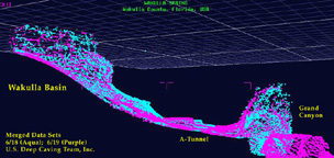
On the Wakulla-2 Expedition surveying is done automatically by a Digital Wall Mapper (DWM) mounted on a Diver Propulsion Vehicle (DPV). The DWM uses an Inertial Navigation System (INS) for determining the position and orientation of the DPV and a Sonar Measurement Device (SMD) that simultaneously measures thirty-two wall distances for determining cross sections. Data are gathered several times per second and the resulting wall points are spaced tens of centimeters apart.

Within the DWM, data from the INS, the SMD, three pressure sensors, and a thermometer are stored in an on-board computer. When the DPV returns to the surface the data are downloaded to a Personal Computer (PC). The PC reformats and writes the data to a zip disk which is then transferred to a Silicon Graphics Inc. (SGI) workstation.

Nine separate programs, written in ANSI C and using SGI-GL for graphics support, comprise the software suite on the SGO workstations. These nine programs provide the following functions:

  • Allow the visualization of the raw data from the DWM for inspection and for editing any obvious problems.
  • Allow the conversion of traverse line data from the INS, in the form of Cartesian coordinates referenced to the start point of the survey run, to the master Cartesian coordinate system established for the cave.
  • Using information from the INS, to convert the radial distance sonar measurements from the SMD to Cartesian coordinates of wall points referenced to the master Cartesian coordinate system established for the cave.
  • To allow the conflation of data from multiple survey runs to improve the accuracy of passage morphology.
  • To convert random passage wall points to sequential cross sections along the cave passages, in order to maximize the efficiency of rendering the passages on the SGI workstation using shaded polygons.
  • To present on the screen of the SGI an interactive 3D map of the cave and its surface environs, for research, interpretation, and study.

About 50,000 lines of custom C-code are required to perform these functions.

Copyright © 2024 U.S. Deep Caving Team, Inc. All rights reserved.
Todo el contenido tiene derechos de autor del U.S. Deep Caving Team. Todos los derechos reservados.
No portion of these pages may be used for any reason without prior written authorization.